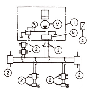
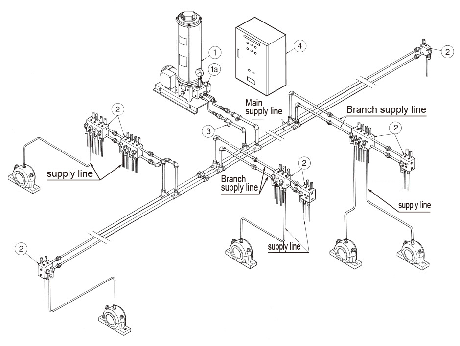
Motor Driven Lance Type System
Features
• Reliable operation with few failures as switching is performed by the lubricating pressure itself. (UE series)
• Simply configured lubrication piping with low piping work costs.
• Low electrical wiring costs as control mechanisms are grouped together at the pump.
• Convenient for maintenance and inspection since pressure can be adjusted on the pump side.
• Suited for medium- and small-size systems where lubrication locations are relatively centralized together.
System Operation
Automatic operation is performed based on the lubrication interval set by the system timer on the electric control panel (4). In addition to the “Tank Empty” and “Overload operation” alarms, the “Oil feed time extension” alarm is displayed by the signal timer to indicate an abnormal lubrication state.
The signal timer is set to roughly twice the completion time of lubrication operation.
The hydraulic operating valve (1a) functions to alternately switch the two main supply lines. When the pump discharge pressure reaches the preset pressure, the hydraulic operating valve (1a) is switched to send a signal to the electric control panel (4) to stop the pump (1).
After a certain period of time has elapsed, the system timer is activated to start lubrication by the main supply line on the opposite side. The lubrication time is planned to normally end within five minutes (max. eight minutes), and the standard set pressure of the hydraulic operating valve is 21 MPa.
Example Circuit Diagram (UE series)


Configuration
| 1 | Pump | UE-**-AN type U-**-AN type |
| 1a | Change over valve | LRV-7 type HV03 type |
| 2 | Distributing valve | DW-20 to 50 type DV-30 to 60 type also can be used. |
| 3 | Y type line strainer | T111-* |
| 4 | Electric control panel | EF type or EA type |
Note) The switching system differs on the U-25AN, U-30AN and U-40AN type motor driven grease pumps.

