In recent years, large-scale manufacturing equipment and facilities such as steel manufacturing facilities are steadily growing in complexity and size.
These facilities have an enormous number of lubrication points, and required lubrication conditions are becoming increasingly severe under such harsh operating conditions as high speed, high loads, and extended operation.
Dual line systems are widely adopted as the most efficient and reliable centralized lubricating systems to automatically supply appropriate lubricating amounts with no errors under very severe environments like these.
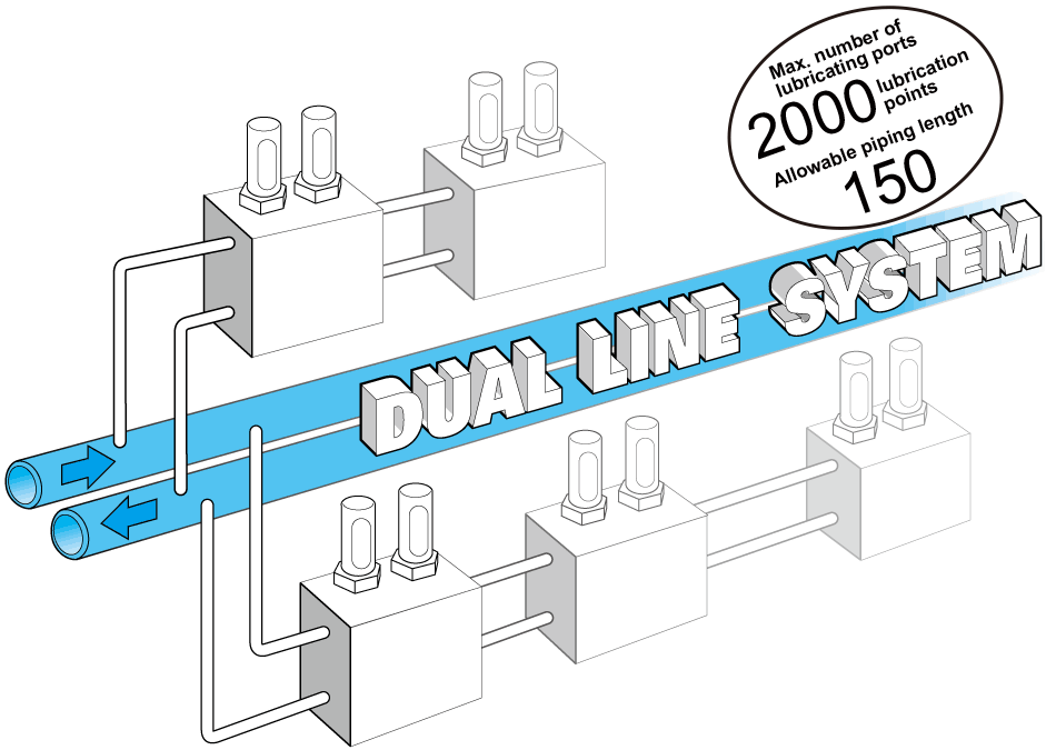
What Is a “Dual Line Centralized Lubricating System?”
This lubricating system is suited to equipment and facilities comprising 50 up to around 2,000 lubricating points connected to a single pump and multiple distributing valves by two piping lines.
Optimal selection of lubricating amount
Dual line systems come with an adjustment mechanism that optimally determines the lubricating amount.
Reliable quantitative distribution
Once selected, the lubricating amount stays the same regardless of environmental factors (bearing resistance, temperature).
System operation assurance
Dual line systems are designed that the operation of distributing valves is assured by the pumping pressure of the lubricant.
Simple piping, wider supply
Piping is simple and allows lubricant to be supplied to locations over wider areas.
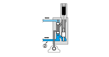
Step 1
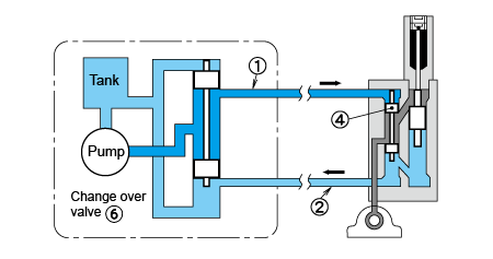
Grease transported from the pump passes through the discharge supply line (1) to reach the pilot piston (4) and pushes down the pilot piston (4).
At this time, the grease on the opposite (lower) side passes through the discharge supply line (2) to be released to the tank.
Step 2
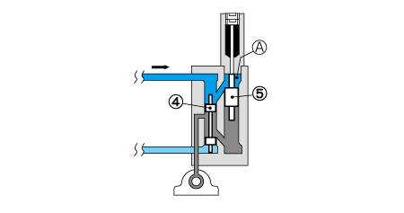
As the pilot piston (4) is increasingly pushed down, the valve internal passage is opened to the upper chamber (A) of the main piston (5). As a result, pumped grease reaches the upper chamber and then pushes down the main piston (5).
Step 3
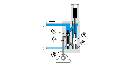
As the main piston (5) is increasingly pushed down, grease in its lower chamber (B) passes through the small-diameter section (C) of the pilot piston (4) to be supplied to the lubrication point from the discharging port (3).
At this time, grease of the stroke amount of the main piston (5) is measured then supplied.
Step 4
Next, the change over valve (6) is switched to feed grease fed under pressure from the pump to the distributing valve from discharge supply line (2). From here, this series of operations from Step 1 is repeated, except that the upper and lower operations are reversed.
